Tool Building Design Assistance
Benefit From Custom Tooling Solutions
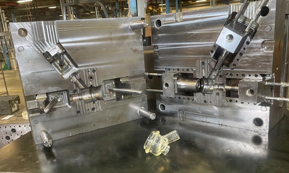
Our strategic tooling partners use CREO software to design tools that produce parts to your exact specifications. With deep experience across a number of industries, we’re able to manufacture high quality tooling optimized for specific market uses. We guarantee that the mold you contract with us to build will produce parts that meet your design specifications.
When designing a tool, we consider a variety of factors, including the number of shots, the specified resin, the projected mold life, and other critical factors. We then build the molds with steel tolerances of +/- 0.003″ or 0.075mm.
We offer the following tooling services.
- Full New Tool Program Management: Covers the complete tool development cycle from tooling concept through the finished manufacture and trial of the production tool.
- Satisfaction Guarantee: We guarantee that you’ll receive molded parts that meet your quoted design specifications for either new mold builds or major mold refurbishments.
- Major Mold Refurbishments: We can fix your ‘problem’ molds so they can produce parts that meet your specifications. We can also modify existing tooling to accomplish design changes that may occur after your product launch.
- Mold Cleaning, Service, and Maintenance: We perform scheduled maintenance on molds to ensure continuous optimal performance.
- Mold Transfers: We can quickly get your molds into production making quality parts whether you are moving them from another domestic plastics shop or is part of your reshoring process.
Request a Free Consultation
Learn With EnTech

At EnTech Plastics, we treat wear resistance as an engineering problem and we consider tribology when specifying resins for custom injection molding.

Performance is engineered. For engineers designing components subject to impacts, drops, vibration and rough handling, understanding the real mechanics of toughness makes all the difference. Resin selection plays a huge role, along with wall geometry and gate location. And it’s not just the materials. It’s the overall design and processing considerations that determine the outcome. Are toughness and strength the same thing when it comes to resin? Impact strength and tensile strength are not interchangeable. While one material might be stiff and strong in tension, it could also be fragile when it comes to impact. Toughness is the ability to absorb energy before fracturing. Even if a part has been vibrated for thousands of hours, this toughness is what keeps it in working condition. On a stress-strain curve, toughness is represented by the area under the curve. Resisting load is one thing, but the material needs to be able to deform plastically before it breaks. Engineers should specify tensile strength, as well as impact strength, notch sensitivity and the effect of temperature on ductile-to-brittle transition. What resin materials perform best in rugged applications? Toughened Nylons (Polyamide 6 and PA66 with Impact Modifiers) Standard nylon is a strong performer but low moisture absorption requirements and notch sensitivity are potential factors to consider. A toughened grade, compounded with elastomeric impact modifiers, often rubber or thermoplastic elastomers dispersed at the microscale, can improve impact resistance while maintaining chemical resistance. For what application would toughened nylon be the best fit? Under-hood and powertrain-adjacent applications where heat and chemical exposure are constants Material handling components like gears, brackets, conveyor parts and wear pads Structural housings that need dimensional stability alongside impact resistance Moisture uptake affects both dimensional stability and mechanical properties. Parts designed in dry-as-molded conditions will behave differently after equilibrium moisture absorption. If the application will involve outdoor exposure in cold temperatures, cold storage conditions or refrigerated environments, verify impact data at operating temperatures, not just the ambient temperature. Note that most toughened nylons retain reasonable impact performance down to around -20°C. Polycarbonate and PC Blends Polycarbonate (PC) is one of the most impact-resistant unfilled engineering resins available. It’s often used in protective equipment and enclosures requiring transparency and high toughness. Unmodified PC is notch sensitive, so fuels and cleaning agents can cause a chemical attack, which leads to cracking. PC blended with acrylonitrile butadiene styrene (ABS) is a high-performance thermoplastic blend. The strength and heat resistance of a PC compliments the processability and ductility of ABS. Costs are also lower. For heavy-duty enclosures, power tool housings and rugged consumer-industrial products, this blend would be ideal. PC blended with Polybutylene Terephthalate (PBT) and PC blended with Acrylonitrile Styrene Acrylate (ASA) would be optimal for outdoor and operating conditions featuring highly corrosive substances that degrade materials like concrete, steel and polymers. ASA has superior UV and weather resistance. Impact values often remain high down to -40°C or below, making it work well for refrigeration, outdoor and cold environments. ABS and Impact-Modified ABS ABS is the go-to for industrial enclosures, housings and structural components. The rubber butadiene phase, dispersed as particles within the SAN matrix, absorbs energy during impact, providing toughness that far exceeds general-purpose styrene resins. Standard ABS is cost effective and offers rigidity, toughness and processability. Impact-modified ABS grades compound additional elastomeric content to shift the balance further toward toughness, at some cost to stiffness and heat deflection temperature. ABS has its constraints like poor UV stability, limited chemical resistance and a reduction in impact performance at lower temperatures that drops off more sharply than PC. ASA (Acrylonitrile Styrene Acrylate) ASA offers similar processing characteristics and toughness profile to ABS while delivering dramatically superior UV and weathering resistance. There is no need for paint or any secondary coating. For outdoor enclosures, agricultural equipment housings, utility infrastructure components and any application with extended sun exposure, ASA is a clear choice. The resin cost is higher and there are slightly lower peak impact values compared to high-impact ABS grades. But by factoring out the cost of UV-protective coatings and the field performance risk of unprotected ABS in outdoor service, ASA still comes out on top regarding total system cost. Why is notch sensitivity important in impact design? Notch sensitivity dictates a material's vulnerability to sudden, brittle fracture at stress concentrators like a sharp corner, a gate vestige, a tooling mark or a snap-fit feature. Design implications are significant: Avoid sharp internal corners Draft angles and ejector pin design matter Snap-fit features require more attention Use notched impact data relevant to your geometry for best results. Why is wall thickness important in impact design? Wall thickness directly dictates a part’s structural integrity, ability to absorb energy and resistance to deformation, warping or cracking. If it’s too thin, it deflects quickly and fractures. The ideal space for unfilled engineering resins in rugged applications tends to be in the 2.5–4.5mm range, with wall-to-rib transitions designed to avoid abrupt cross-section changes. Ribs should be 50–70% of nominal wall thickness to avoid sink while still adding structural contribution. Uniform wall thickness across a part should always be the goal. Why is the geometry of a part an active contributor to its impact performance? The geometry of a part is an active contributor to impact performance by dictating how kinetic energy is dissipated through deformation modes. Closed cross-sections are better than open ones to improve stiffness-to-weight and energy absorption Gussets and radii work well together Weld lines are weak points, locate them away from high-stress zones Deep texture, logos and sharp embossing features can all act as stress concentrators, understand the impact How should I factor in the UV exposure profile when choosing materials? UV radiation breaks polymer chains, leading to surface chalking, color shift, embrittlement and ultimately loss of mechanical performance. Review your UV exposure profile. Short-term or protected (shaded) outdoor exposure? UV-stabilized ABS/PC grades (with UV absorbers added to the compound) Extended outdoor exposure in full sun? ASA is the first recommendation for thermoplastics expected to survive 5-10+ years of uncoated outdoor service without significant mechanical degradation Optical clarity or peak impact performance? PC/ASA blends/UV-stabilized PC grades Pigmentation consideration? Carbon black is the most effective UV stabilizer Designing for impact resistance isn't a single material decision, it's the integration of resin selection, part geometry, tooling design and processing discipline into a system that performs reliably in the real world. At EnTech Plastics, our engineers engage at the Design for Manufacturing stage specifically to identify where impact performance is at risk and what changes in geometry, material specification or processing approach will resolve it. If you're developing a component for protective equipment, rugged enclosures, material handling and have questions, reach out to discuss your specific needs. Contact EnTech Plastics today.

A component fails in the field. A part is cracked or warped and now an expensive recall is in place. When investigated, the design was correct, the molding was properly done, dimensional integrity was in check, and the surface finish was fine. What happened? Improper material selection. Commodity-grade plastics (your standard polypropylenes, polyethylenes and general-purpose Acrylonitrile Butadiene Styrene) are workhorses for the right applications. But when a component faces aggressive chemistry, sustained heat, mechanical fatigue or UV exposure, commodity resins reach their limits fast. That’s where high-performance engineered resins come in. And that’s where engineered resin selection becomes an essential engineering discipline. Choosing the right engineered resin for industrial applications is vital to success in the field. Start With an Environmental Exposure Profile What does this part actually have to do? Think about the entire lifespan and scenarios that aren’t common, but could still occur. Map exposures through the following five categories: Thermal, Chemical, Mechanical, Environmental and Regulatory. Thermal . Think about temperatures and how frequently does the part thermal cycle? Chemical. Cleaning agents, coolants, maintenance fluids? What chemicals could come in contact with the part? Mechanical. What type of loading is the part under? Static, dynamic, impact? Where are stress concentrations? Environmental. Is the part outside? Will it be in extreme heat and humidity? UV? Regulatory. Are there flame ratings (UL94), FDA compliance requirements or industry certifications that constrain the material field? This is the process that results in a confident engineered resin selection rather than a resin selection based on guesswork. Prioritize Competing Requirements No engineered resin is going to be the clear favorite for all of the competing requirements a component may have, but with knowledge and analysis, you will still be able to make an informed selection. Let’s review some of the most common competing requirements engineers face in extreme industrial applications. Chemical resistance vs. impact strength. Highly chemically resistant resins like Polyphenylene Sulfide (PPS) deliver exceptional resistance to a broad array of fuels, oils, solvents, acids, and bases in operating environments up to 200°C, but they can be brittle without impact modification. Understanding which failure mode is most consequential drives the balance. Heat resistance vs. processability. (Polyether ether ketone) PEEK’s continuous use temperature ceiling is unmatched in the thermoplastic world, but it demands elevated barrel temperatures, precise mold temperature control and processing expertise that not every molder can deliver. Dimensional stability vs. moisture absorption. Nylons offer outstanding mechanical properties and wear resistance, but they absorb moisture, which affects tolerances. In precision applications or humid environments, Polybutylene Terephthalate (PBT) or (Polyoxymethylene) (POM) may be the more reliable choice. Flame retardancy vs. mechanical performance. Flame retardant (FR) additives can reduce impact resistance and affect surface aesthetics. A UL94 V-0 requirement (the most stringent vertical flammability rating for plastics) may eliminate certain resin families outright. Rank requirements by consequence of failure. If the failure causes issues like a regulatory violation or a line shutdown, this is the most important consideration. Everything else is optimized around it. Match the Resin to the Scenario Now that you’ve built your exposure profiles and ranked your requirements, let’s take a look at some common industrial scenarios and develop a decision path for each. Chemical Processing Equipment : Custom injection molded equipment such as pump housings/casings, reactors, valve bodies, fluid manifolds, etc. Ask yourself chemical related questions. What will the part come into contact with? What are the continuous and peak operating temperatures? Is steam cleaning or autoclave exposure involved? Is mechanical load significant enough to require glass fill? Determine the best candidates for the job. PPS for the chemical resistance and flame retardancy. PEEK where the most severe chemical and thermal demands intersect. PSU where hydrolytic stability and steam resistance are the governing requirements. Outdoor Industrial Equipment: Agricultural machinery, injection molded trucking components, utility enclosures and other industrial plastic components. Ask yourself about UV and weathering exposure. Think about the impact of cold weather. What fluid exposures (fuels, hydraulic fluid, lubricants) are present? Do tight tolerances make moisture absorption a dimensional risk? Determine the best candidates for the job. UV-stabilized or glass-filled nylon for structural mechanical components. PBT where moisture sensitivity and chemical resistance matter. POM for precision mechanical parts requiring low friction and fatigue resistance. PC/ABS for enclosures requiring impact performance and dimensional stability. High-Temperature Machinery: Engine bay components, heated process equipment, thermal management housings, etc. Ask yourself what is the required continuous service temperature? Is thermal cycling a significant factor? Do chemical and thermal demands combine in a way that narrows the field to the high-temperature injection molding resins tier? Determine your most likely candidates. PEI (Ultem) for continuous use to approximately 170°C with strong dimensional stability and inherent flame retardancy. PPS for applications requiring both elevated temperature resistance and broad chemical resistance up to approximately 220°C. PEEK for the most demanding tier. Filled and Reinforced Grades Selecting a resin family is only the first decision. Selecting the right grade within that family matters just as much. Glass-filled nylon injection molding and other filled engineered resins, including mineral and carbon fiber reinforced grades, significantly improve stiffness, tensile strength and dimensional stability at temperature. Impact modifiers can address brittleness in otherwise high-performing resins like PPS. Abrasive fillers like glass and carbon fiber accelerate tool wear and may require hardened steel or specialized coatings. The Molder Is Part of the Material Decision Once you have the right resin, you have to think about the actual process that resin is about to undergo. At EnTech, resin selection is part of the engineering conversation from the very beginning. We’ve performed resin evaluations and substitutions that resolved chronic field failures, helped customers navigate material trade-offs they hadn’t fully mapped and processed some of the most demanding thermoplastics in commercial use. The resin and the process are equally part of the solution. Map the environment. Rank the requirements by consequence of failure. Narrow to the resin families that address the governing criteria. Validate against your specific scenario and do it with a custom injection molding partner who understands that material selection and process engineering are the same conversation. Ready to work through your material selection challenge? Contact EnTech's engineering team for a free consultation .